3D-Printed Garrison Binder
A Garrison-style rod binder built almost entirely from 3D-printed parts. The architecture follows E. Garrison’s original — vertical face board, cradle on the top edge with a belt gap, guide wheels and drive wheel on the face, a weight riding the belt’s slack loop, and a disc-drag cord tensioner — as documented in detail on the Garrison Binder page. Read that page first; all of its tuning guidance applies directly to this build.
Every wheel runs on two 608 skateboard bearings. All bolt holes, counterbores, captive-nut pockets, and adjustment slots are printed in place — the only drilling in this project is a handful of holes in the wooden face board.
How it works
Crank the drive wheel → the belt circulates → the full turn of belt around the rod spins it → the binding cord (spool → eye 1 → tensioner → eye 2) wraps onto the spinning rod as you feed it through the cradle. The weight keeps constant belt pressure regardless of crank speed. Guide 3 sits just below the cradle on the drive side so the belt’s return run enters the gap vertically instead of scraping the left cradle block.
Printed parts
All STLs are exported already in print orientation — import, slice, print. No supports needed on any part. (One caveat: the feed head’s dowel socket ceiling is a flat internal bridge — it prints fine, and it lands on the non-critical dowel end face.)
| Part | Qty | STL | Preview |
|---|---|---|---|
| Drive wheel (Ø64) | 1 | drive_wheel.stl | 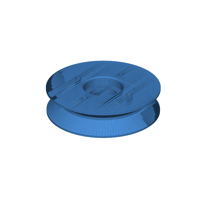 |
| Idler wheel (Ø40) | 4 | idler_wheel.stl | 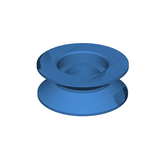 |
| Bearing spacer | 5 | bearing_spacer.stl | 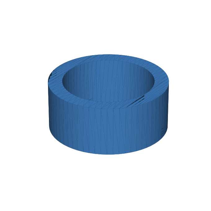 |
| Cradle block | 2 | cradle_block.stl | 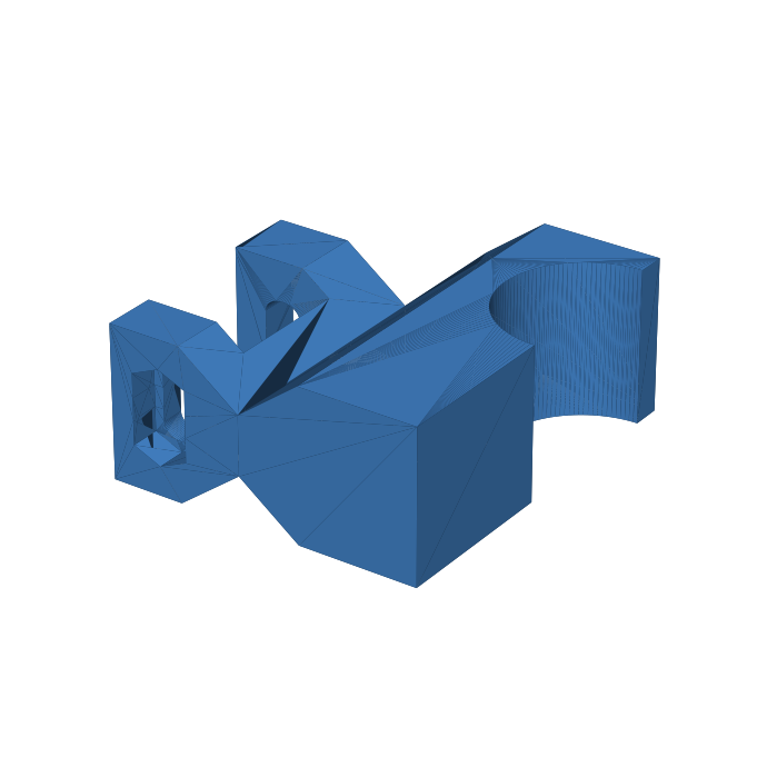 |
| Feed-support head | 2 | feed_head.stl | 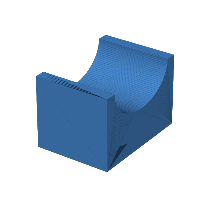 |
| Feed-support base | 2 | feed_base.stl | 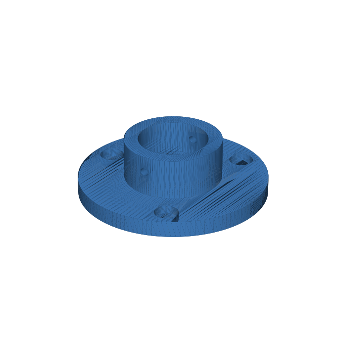 |
| Crank arm | 1 | crank_arm.stl | 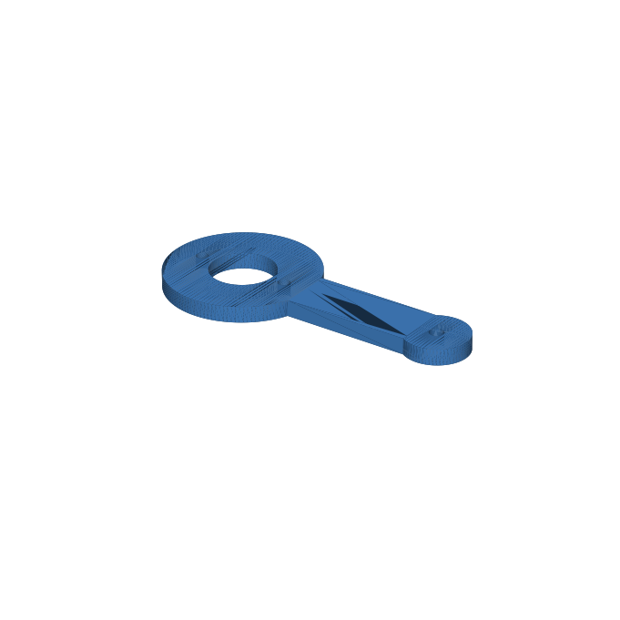 |
| Crank grip | 1 | crank_grip.stl | 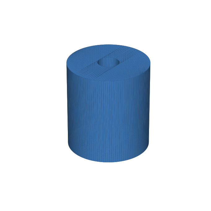 |
| Weight hanger | 1 | weight_hanger.stl | 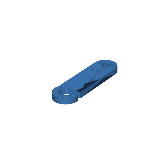 |
| Tensioner base | 1 | tensioner_base.stl | 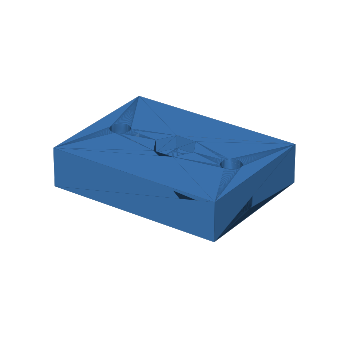 |
| Tensioner disc | 2 | tensioner_disc.stl | 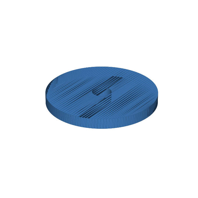 |
| Tensioner knob | 1 | tensioner_knob.stl | 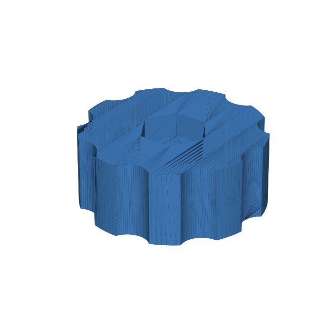 |
| Cord guide post | 2 | cord_guide.stl | 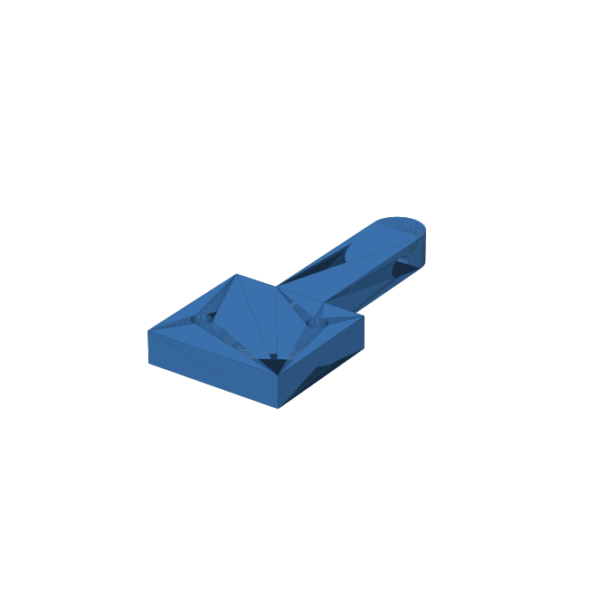 |
| Spool bracket | 2 | spool_bracket.stl | 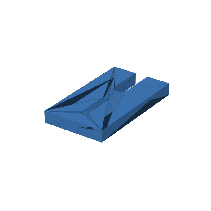 |
| Board foot | 2 | board_foot.stl | 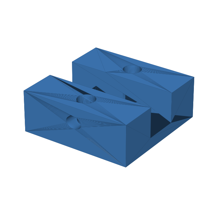 |
Parametric source: generate_binder_stls.py. All dimensions (board thickness, bearing fit, trough size, belt diameter) are parameters at the top of the script — pip install manifold3d trimesh numpy matplotlib and re-run to regenerate every STL for your hardware. The script validates that every mesh is watertight before export.
Print settings
| Setting | Value |
|---|---|
| Material | PETG (PLA acceptable for non-wheel parts) |
| Layer height | 0.2 mm |
| Perimeters | 4 |
| Infill | 40% (wheels and cradle: 60%) |
| Supports | None |
The bearing pockets are sized at Ø22.15 for a light press fit. Print one idler first and test: if the bearing falls out, reduce POCKET_D to 22.05 and regenerate; if it won’t seat with firm thumb pressure, raise it to 22.25.
Hardware
| Item | Qty | Used for |
|---|---|---|
| 608-2RS bearings (8×22×7) | 10 | 2 per wheel |
| M8 × 60 bolts + nyloc nuts | 4 | drive + 3 guide wheel axles (through board) |
| M8 × 50 bolt + nyloc nut | 1 | weight-pulley axle (through hanger) |
| M8 × 80 bolt (or rod) + washers | 1 | spool axle |
| M8 washers | 16 | axle stacks |
| M5 × 40 bolts + hex nuts | 2 | cradle clamp bolts (hex or socket head — the counterbore fits an 8 mm socket) |
| M5 × 45 bolt + hex nut | 1 | tensioner stack |
| M5 × 50 bolt + nyloc nut | 1 | crank handle (grip spins on shank) |
| M4 × 25 screws | 2 | crank arm → drive wheel (self-tap into printed pilots) |
| M4 × 10 screws | 6 | pinch screws: feed heads ×2, feed bases ×2, board feet ×2 (all counterbored) |
| #8 × 3/4" wood screws | ~20 | tensioner, cord guides, spool brackets, feet, feed bases |
| Compression spring ~Ø10 × 15 | 1 | tensioner (smooth drag adjustment) |
| Face board: 500 × 300 × 18 mm ply | 1 | measure actual thickness — see note |
| Mounting plank: ~600 × 200 mm ply | 1 | feet screw to this; it overhangs the bench edge |
| 1" hardwood dowel | ~650 mm | feed-support posts, cut to height |
| 3/16" braided mason line | 2 m | drive belt (braided, not twisted) |
| 1/8" brass rod, ~300 mm | 1 | optional: fly-off take-off loop above the spool (per the article) |
| Rodmaker’s binding cord | 1 spool | |
| Small jar + hardware | 1 | weight, 450–680 g (1–1.5 lb per the article) |
Board thickness note: the cradle channel and foot slots are generated for 18.0 mm stock + 0.35 mm clearance. Plywood sold as 3/4" varies from 17.5–19 mm — measure yours and set BOARD_T in the script before printing the cradles and feet.
Board drilling plan
The only drilled holes in the project. Coordinates are (distance from the board’s left edge, distance down from the top edge) on a 500 × 300 board:
| Hole | Position | Size | For |
|---|---|---|---|
| Cradle bolt L | (232, 7.5) | Ø5.5 | M5 clamp bolt |
| Cradle bolt R | (268, 7.5) | Ø5.5 | M5 clamp bolt |
| Drive wheel | (150, 150) | Ø8.5 | M8 axle |
| Guide wheel 1 | (300, 130) | Ø8.5 | M8 axle — sets the belt’s exit angle: the outgoing strand departs the rod at ~168° of wrap |
| Guide wheel 2 | (330, 250) | Ø8.5 | M8 axle |
| Guide wheel 3 | (262, 190) | Ø8.5 | M8 axle — brings the return strand into the gap vertically |
Everything else attaches with wood screws through printed counterbores — no drilling, just drive the screws.
Assembly
1. Feet and board
Screw the two board feet to the mounting plank ~400 mm apart, slots aligned, then clamp the plank to the bench so the board’s front face overhangs the bench edge by at least 25 mm. The belt plane runs 12 mm in front of the board face and the weight loop hangs below the board — both need clear air in front of the bench edge along the whole loop span. Drop the board into the slots and drive the pinch screws.
2. Wheels
Press two 608 bearings into each wheel with a vise or thumb pressure. Drop a printed spacer between them (it clamps between the inner races so the nyloc can be fully torqued without binding the wheel).
Axle stack, inside to out: bolt head → washer → board → washer → bearing/wheel/bearing → washer → nyloc. Torque the nut fully — the spacer takes the clamp load and the wheel spins free.
Fasten the crank arm to the drive wheel face with two M4 × 25 screws — they self-tap into the printed pilot holes (any two opposite pilots) and stop inside the wheel, so nothing protrudes from the back face spinning next to the board. Then bolt the grip to the arm end with the M5 — nyloc snug but the grip must spin.
3. Cradle
Drop the two cradle blocks over the board’s top edge, one each side of the belt-gap position. Each clamps with an M5 bolt through the printed slot — the hex nut sits captive in the track on the back face. The slots give ±4.5 mm of slide per block: start with a 6 mm gap between the blocks (within the article’s 3/16–1/4" range, with a little margin around the 4.8 mm belt) and close it down later only if the cord-wrap spacing demands it. The gap-facing bottom edges of each trough slab carry printed 45° relief chamfers so the departing belt clears the blocks.
The trough axis sits 12 mm in front of the board face — the same plane as the wheel grooves. This is by design; don’t shim it.
4. Drive belt
Make a knotless loop from the mason line (this is the same splice described in the Garrison Binder article):
- Thread one end 50 mm into the eye of a large needle.
- Push the needle into the hollow braided core of the other end, run it 40 mm inside, and out.
- Pull the tail through until the free end disappears into the splice; stitch across it twice.
Route: around the rod one full turn at the cradle gap → down to guide 1 → guide 2 → across the slack loop (weight hanger + pulley riding in it) → up over the drive wheel → guide 3 → vertically back up into the gap to the rod. Splice the loop to length in place so the weight hangs with ~150 mm of travel.
5. Cord path
Screw the spool brackets to the face at the left end (~60 mm apart); the spool rides on the M8 axle resting in the open slots. Screw eye 1 to the face at ~130 mm from the left edge with its flange top flush with the board’s top edge (eye at rod height, guiding the spool run). Screw eye 2 at ~225 mm with its flange top ~30 mm below the edge — from there the cord rises to the bind point at roughly 50°. The tensioner goes between them at (170, 50): cord runs spool → eye 1 → down between the tensioner discs → eye 2 → up onto the rod.
Per the article, the cord must approach the rod from the in-feed side, rising at a steep angle — never straight down, and never from the out-feed side. Eye 2 sitting low and left of the cradle delivers this.
Tensioner stack on the M5 bolt: captive head in base → base → disc → cord → disc → spring → knob (captive nut, pocket facing the spring). The knob compresses the spring for fine, stable drag.
6. Feed supports
Cut two 1" dowels to length: measure H = bench top to the bottom of the cradle trough, then cut dowels to H − 24 mm. Push into base and head sockets, drive the pinch screws. The big 1¾" troughs end up level with the cradle trough bottom — exactly the alignment the article calls for. The base flanges have screw holes; leave them unscrewed if you want to reposition the stands between butt and tip sections.
Tuning
All of the Garrison Binder tuning advice applies. The short version:
- Weight: start at ~450 g (1 lb). More is not better — if the rod drags in the cradle or the corners chip, remove weight.
- Cord tension: must be less than the belt weight. Test per the article — tie a loop in the cord and hang the weight on it; the weight should pull cord off the spool easily. Too much cord tension twists the rod on the first pass.
- Spool take-off drag: cord pulling the spool round adds hidden tension upstream of the tensioner, and it grows as the spool empties — the exact problem the article describes. Its fix works here too: bend the 1/8" brass rod into a loop rising above the spool and take the cord off over the end through it; the springy rod also absorbs tension spikes.
- Belt clearance: if the belt rubs a cradle block, widen the gap slightly or nudge guide 1 further from the cradle — the belt leaving the rod should angle away, never scrape. With guide 1 at the drilling-plan position the belt departs at ~168° of wrap, inside the article’s ≤170° rule, and the cradle chamfers give it clear air.
- Bind twice, once in each direction, per standard Garrison practice.
Related
- Garrison Binder — the reference article: theory, tuning, and troubleshooting
- Rod Binder Notes — Smithwick binder and a gallery of other designs
- ‘New’ Smithwick Binder — my first (wooden) binder build