Ring-Flyer Orbit Binder (Design Study)
A hypothetical rod binder that inverts the Garrison principle: instead of a belt spinning the rod while the cord stands still, the rod never rotates — the cord spool orbits around it, the way a cable-serving machine or coil winder lays wire. This page is a design study: the parts are fully engineered and printable, but the machine has not been built yet. Read it alongside the Garrison Binder article and the printed Garrison binder build, which this design deliberately argues with.
This concept won a three-way design comparison against a counter-rotating twin-cord binder (fatal flaw: the wrap zone between the rotors can’t be hand-steadied, and its twist cancellation silently drifts as the friction drags wear) and a rotisserie chuck-and-leadscrew machine (fatal flaw: driving a wet 2 mm tip section from one end winds radians of torsion into it — the exact defect a binder exists to prevent).
How it works
The rod section rests in two height-adjustable V supports, passing through the ring’s Ø90 bore without touching it. The ring rides on four V-grooved rollers that engage a 90°-included V-ridge on its rim — the V-in-V contact locates the ring both radially and axially.
The ring has two drive inputs:
- Primary — the spinner knob bolted to the ring face: whirl the ring directly, like spinning a valve wheel. One revolution = one wrap; a comfortable 2–3 rev/s covers a 1.3 m section in about 90–130 seconds.
- Fine — the geared pinion crank: a 26-tooth pinion meshing with the ring’s 78-tooth gear gives a 3:1 reduction — three crank turns per wrap. Too slow for whole sections, exactly right for creeping along a fragile 2 mm tip at low tension with full control.
The spool, a disc-drag tensioner, a guide pin, and a fairlead eye all bolt to the ring’s front face and orbit with it. As you drive the ring with one hand and draw the rod through the bore with the other, the fairlead lays binding cord onto the stationary rod in a helix. Wrap pitch = feed speed ÷ wrap rate, exactly the same hand-controlled pitch as a Garrison binder.
The physics
Binding pressure comes purely from cord tension. Hoop pressure on the glue-up is roughly T / (R × pitch) — tension divided by rod radius times wrap spacing. That relationship is kind to tips: a 2 mm tip at 150 g and a tight 3.5 mm pitch sees more consolidation pressure (~430 kPa) than a 10 mm butt at 500 g and 5 mm pitch (~200 kPa). So the tensioner needs only two marked presets — TIP (~150–200 g) and BUTT (~450–550 g) — calibrated once with a spring scale.
The only torque the section ever feels is cord tension × rod radius, about 2–27 N·mm across the tension and diameter range — resisted trivially by the feeding hand. Garrison’s primary twist mechanism (belt tension torquing the strips against cord drag) is eliminated by construction.
Pros and cons vs the Garrison binder
Pros
- No rod rotation → no rotation-induced twist. The failure mode the Garrison article spends most of its words tuning away doesn’t exist here.
- No drive belt. The knotless splice, the ≤170° first-guide rule, belt drag on the cradle, and epoxy-crusted belts all disappear. Only the cord and two V-grooves touch wet glue.
- One tension, not two coupled ones. Garrison tuning balances belt weight against cord drag. Here a single spring-set drag does everything — and spring (not gravity) drag means tension is identical at every ring orientation.
- Repeatable presets. TIP/BUTT marks on the knob, instead of re-tuning a weight jar between sections.
- Instant opposite-hand second pass. No re-rigging — see the operating notes.
- Self-contained cord path. Spool → guide → tensioner → fairlead spans ~100 mm, all orbiting together. No bench-mounted spool alignment, no long cord spans to snag.
- Compact: ~600 mm of bench, the same ten-bearing budget as the printed Garrison build.
Cons
- No belt pre-consolidation. Garrison’s weighted belt kneads the strips together before the cord locks them; here cord tension alone must seat the strips. Butts may need the high preset plus a firm hand-squeeze just ahead of the wrap point.
- Closed ring = end-first threading. You can’t drop a section in mid-length or rescue one sideways mid-bind.
- A rotating assembly must be balanced. The counterweight cup is a genuine setup step; Garrison has no such requirement.
- Rod centring matters. More than ~2–3 mm off the ring axis and the cord payout length fluctuates once per orbit, rippling the tension. Hence the adjustable supports and the centring gauge. Garrison is completely insensitive to this.
- The Ø160 ring is a demanding print. Gear-tooth quality and race runout are at the mercy of printer calibration; Garrison’s plain wheels are forgiving.
- Small onboard spool (~15 m) must be rewound from the bulk spool.
- Speed cap ~3 wraps/s — beyond that the orbiting cord balloons. A Garrison binder cranks as fast as you dare.
Design notes
- Why a closed ring? Cable-serving machines use split rings because cables are endless. Rod sections are finite sticks — they thread through the bore end-first, so the ring can stay closed, keeping the gear teeth and V-race continuous. That continuity is what makes both features printable and smooth.
- Why V-in-V? The 90° ridge running in 90° grooved rollers constrains the ring radially and axially with four small contact patches — no thrust bearing needed, and roller preload is set by one slotted axle.
- Two drives, honestly: a 26T pinion cannot speed-multiply a 78T ring — the gear train is a 3:1 reduction, useful only as a fine drive. Production binding runs on the direct spinner knob at 1:1. (An earlier draft of this concept claimed “one crank = three wraps”; that’s the ratio backwards.)
- Gearing: module 2, 20° pressure angle, 78:26, tooth gaps traced on the true root circle. Each gear is thinned 0.125 mm for a designed 0.25 mm total FDM backlash; the generated profiles measure 0.252 mm working backlash and roll through mesh with zero interference at the 104 mm centre distance. Grease the mesh and run it in for a minute before first use.
- Roller preload: the two top roller axles sit in radial slots. Inward travel is deliberately limited to 0.75 mm — enough to take up all print tolerance in the V-race, not enough to push the standoff tubes into the orbiting gear teeth (verified: zero interference even at full preload).
- Balance: the spool + tensioner cluster is offset on the ring face; the counterweight cup sits diametrically opposite, filled with steel nuts until the ring has no preferred rest position. Spring drag means tension doesn’t care about orientation — balance is purely about smooth cranking.
- Helix-hand kinematics (the subtle one): helix hand flips when either the orbit direction or the feed direction reverses — but not both. Feeding the rod back through while cranking the same direction lays the opposite-hand helix for pass 2 with zero re-rigging. Reversing both (the intuitive move) lays the same hand again.
- The fairlead eye is the one surface the cord saws across under full drag. The printed eye has chamfered edges, but layer lines are layer lines: wax it, flame-polish it, or press a wire/ceramic eyelet in before binding real work.
Printed parts
All meshes are generated parametrically, validated watertight, and export in print orientation.
| Part | Qty | STL | Preview |
|---|---|---|---|
| Orbit ring (Ø160, 78T gear + V-race) | 1 | orbit_ring.stl | 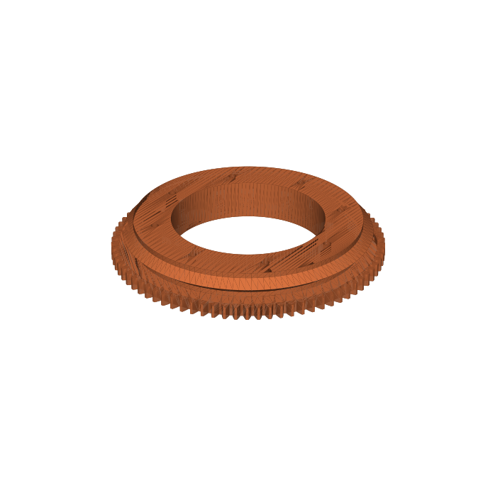 |
| Stanchion plate | 1 | stanchion_plate.stl | 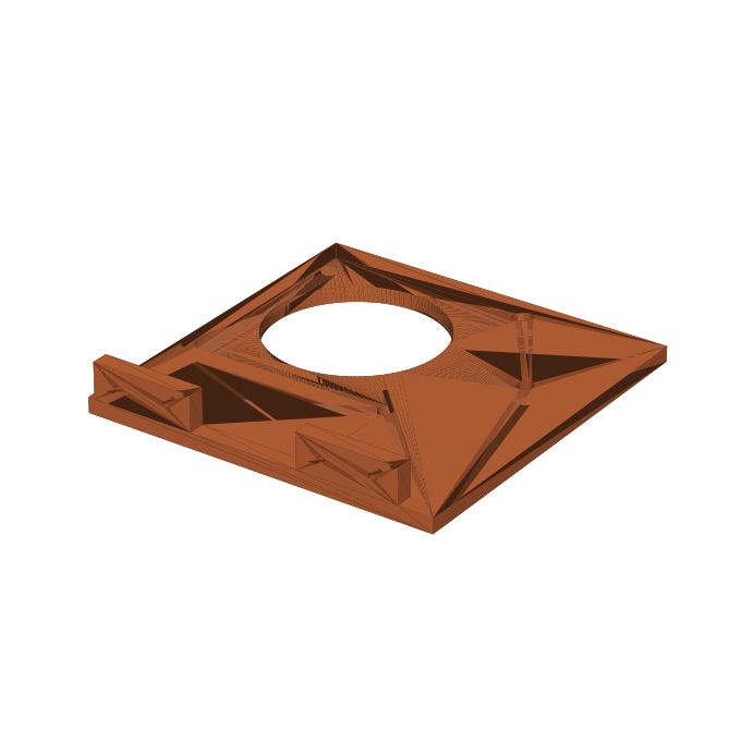 |
| V-roller | 4 | v_roller.stl | 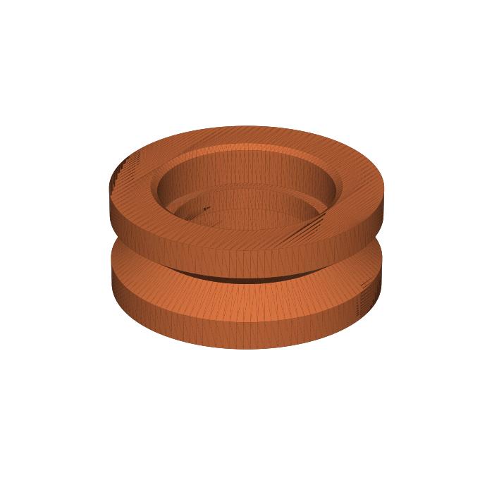 |
| Roller bearing spacer | 4 | roller_spacer.stl | |
| Roller standoff | 4 | roller_standoff.stl |  |
| Pinion + crank hub (26T) | 1 | pinion_crank.stl | 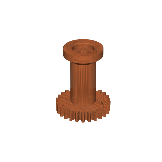 |
| Pinion bearing spacer | 1 | pinion_spacer.stl | |
| Pinion shim | 1 | pinion_shim.stl | |
| Crank arm | 1 | crank_arm.stl | 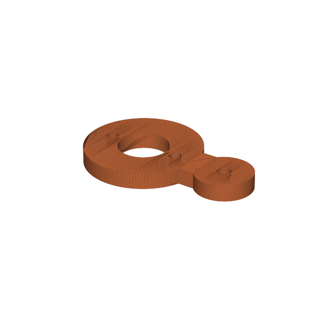 |
| Crank grip | 1 | crank_grip.stl | 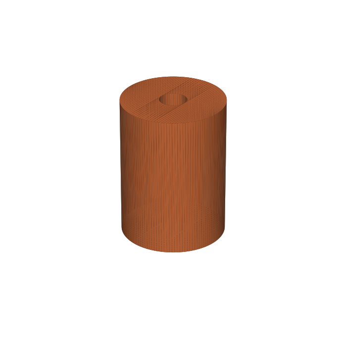 |
| Drive-knob post | 1 | knob_post.stl | 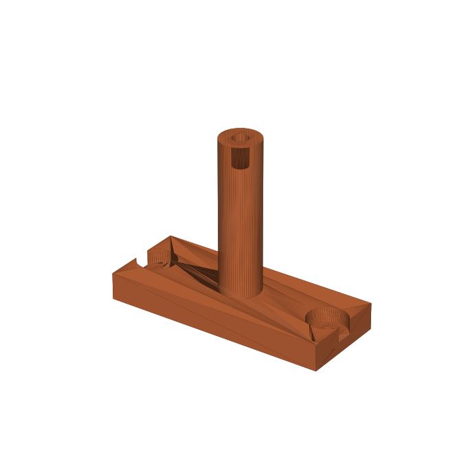 |
| Drive-knob sleeve | 1 | knob_sleeve.stl | 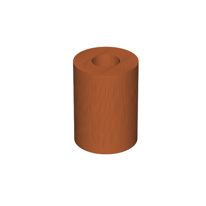 |
| Spool post | 1 | spool_post.stl |  |
| Cord spool | 1 | spool.stl | 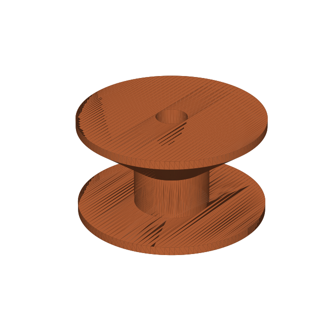 |
| Tensioner base | 1 | tensioner_base.stl |  |
| Tensioner disc | 2 | tensioner_disc.stl | 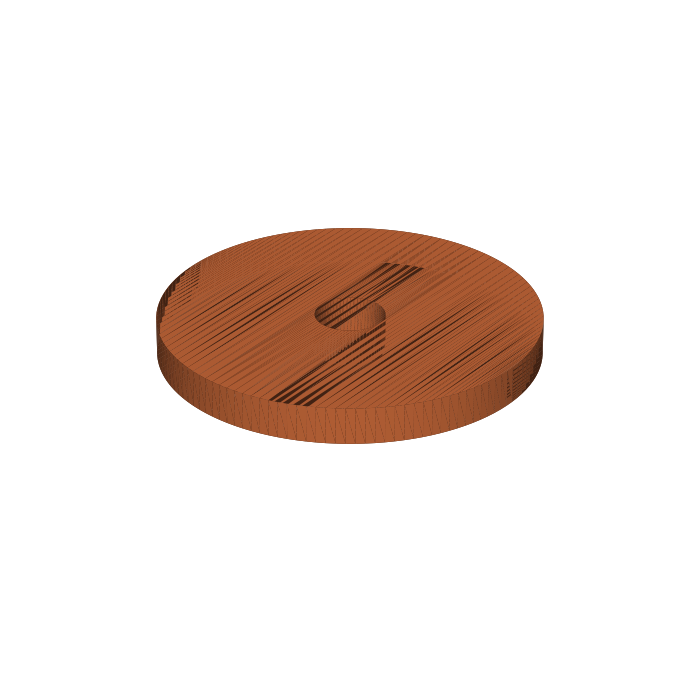 |
| Tensioner knob | 1 | tensioner_knob.stl | 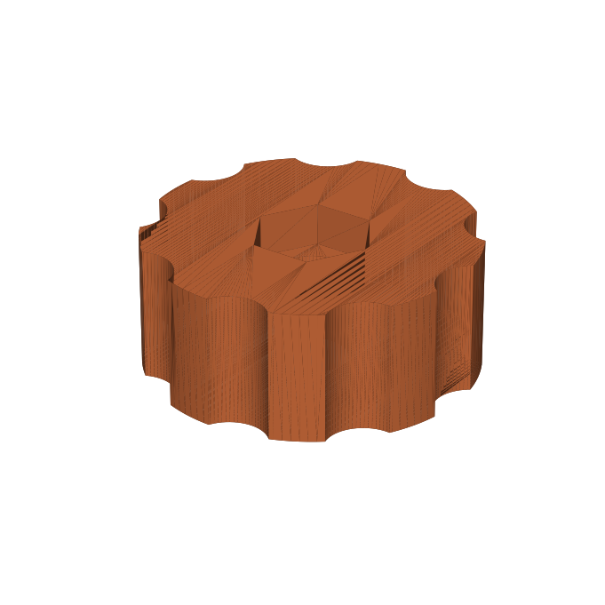 |
| Guide pin | 1 | guide_pin.stl | 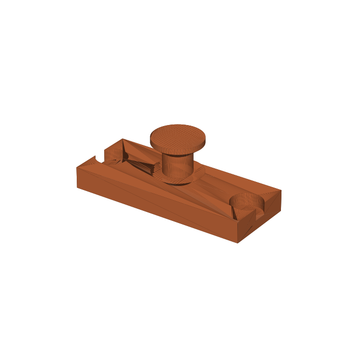 |
| Fairlead | 1 | fairlead.stl | 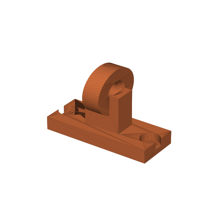 |
| Counterweight cup | 1 | counterweight_cup.stl | 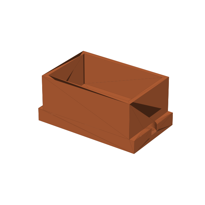 |
| Rod-support head | 2 | support_head.stl | 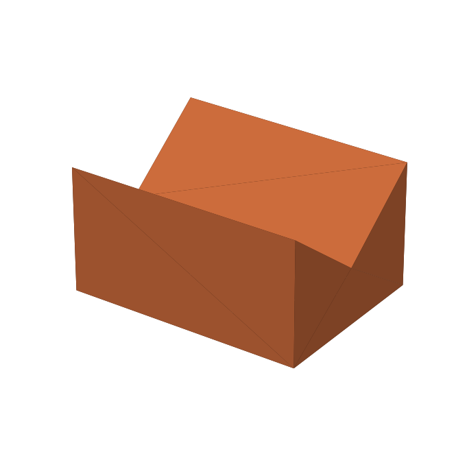 |
| Rod-support base | 2 | support_base.stl | 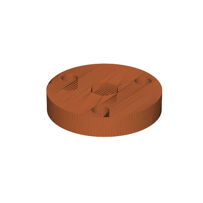 |
| Centring gauge | 1 | centering_gauge.stl | 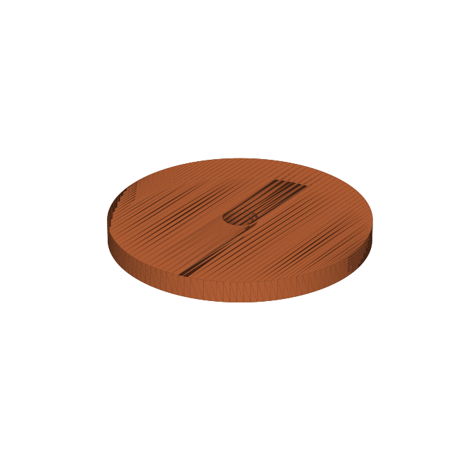 |
Parametric source: generate_ring_flyer_stls.py — same toolchain as the Garrison build (pip install manifold3d trimesh numpy matplotlib, run, done). Bearing-pocket fit uses the same Ø22.15 tuning rule.
Print PETG throughout; the ring and pinion want 5 perimeters and 40–50% infill, seam randomized on the race and teeth, and the plate needs a well-calibrated first layer (it’s a near-full-bed print — a two-piece split is the fallback if yours warps).
Hardware
| Item | Qty | Used for |
|---|---|---|
| 608-2RS bearings | 10 | 4 rollers ×2, pinion ×2 |
| M8 × 65 bolts + nyloc + washers | 5 | roller axles (4, through plate + standoffs) and spool axle (1) |
| M8 × 120 bolt (or M8 rod + nuts) | 1 | pinion axle (printed shim between plate and lower bearing) |
| M8 threaded rod ~150 mm + 4 nuts | 2 | rod-support columns (thread into head/base nuts, jam to lock) |
| M5 × 45 bolt + nut + spring ~Ø10×15 | 1 | tensioner stack |
| M5 × 60 bolt + nyloc | 1 | crank grip (spins on the shank) |
| M4 × 16 screws | 2 | crank arm → pinion flange (self-tap into 14 mm pilots) |
| M4 × 20 bolts + nuts | ~12 | ring furniture — drop each nut down its rear hex shaft, thread the bolt from the front |
| M4 × 10 screw + washer | 1 | drive-knob sleeve retainer |
| #8 wood screws | ~10 | plate feet + support bases |
| Base board ~600 × 250 × 18 mm | 1 | |
| Steel nuts ~150 g | — | counterweight fill |
| Binding cord + spring scale | — | rewind ~15 m onto the printed spool; calibrate presets once |
Setup and operation
- Mount: screw the plate feet and the two support bases to the board, supports ~200 mm each side of the plate.
- Rollers: bearings + spacer into each roller; bolt through plate + standoff. The two top axles sit in radial slots — snug them so the ring turns freely with no rattle.
- Centre the rod line: drop the centring gauge into the ring bore, slide a scrap strip into the matching hex step, and spin the support heads up their columns until the strip sits centred; lock the jam nuts.
- Balance: bolt on the furniture (including the drive knob), then add nuts to the counterweight cup until the ring has no preferred rest position.
- Calibrate: pull cord through the fairlead against a spring scale; mark TIP and BUTT knob positions.
- Bind, pass 1: thread the glued section tip-first through the bore, anchor the cord tail under three hand wraps, then spin the ring by its knob at ≤2–3 rev/s (= 2–3 wraps/s) while drawing the section through at ~10–15 mm/s for a ~5 mm pitch. Switch to the pinion crank (3 turns per wrap) for slow, precise work near the tip.
- Tie off: two half-hitches. Pass 2: drive the ring the same direction and feed the section back through — that flips the helix hand (reversing both flips nothing). Tie off, sight straight, hang to cure.
Open questions (why this is still hypothetical)
- Does cord tension alone consolidate imperfect butt strips without the belt’s kneading action? If not, the fix is a sprung follower roller — added complexity.
- Will printed gear mesh and race seams produce visible wrap-spacing bands? Mitigations: seam randomization, sanding, grease, run-in. Fallback: a TPU friction-ring drive in place of the gear mesh.
- PETG creep in the bearing pockets over months — same known issue and same reprint fix as the Garrison build.
Related
- 3D-Printed Garrison Binder — the conventional build this argues with
- Garrison Binder — the reference article
- Rod Binder Notes — more binder designs