3D-Printed Shop Tools
Printable jigs and shop tools for woodworking projects — the woodworking counterpart to the rodmaking tool set. This page covers the printed parts that the Adjustable Scarf Jig and the DW745 Mobile Saw Cart plans already call for, plus table-saw accessories that fit any SawStop (they key off the standard ¾″ × ⅜″ miter slot and the flat table, not a model).
All are FDM-printable, generated parametrically, and validated watertight. STLs export in print orientation. Print in PETG (or ASA for the saw-cart parts that live in a hot garage), 4+ perimeters, 40% infill — the ratio gauge at 100%.
Parametric source: generate_woodworking_stls.py — edit the parameter block and re-run (pip install manifold3d trimesh numpy matplotlib). The scarf-jig parts come straight from the plan’s dimensions. The saw-cart parts depend on your saw’s feet, dust port and hose, and the values in the script are estimates — measure yours and regenerate.
Scarf jig
Ratio setting gauge
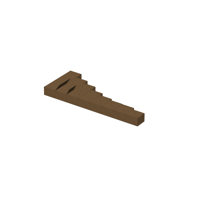
For: setting the bed’s drop d (= 12″ ÷ ratio) without calipers.
A stepped block whose steps are exactly the drop at the 12″ mark for each ratio, tallest to shortest:
| Step | Ratio | Height |
|---|---|---|
| 1 | 1:8 | 1.500″ (38.1 mm) |
| 2 | 1:10 | 1.200″ (30.5 mm) |
| 3 | 1:12 | 1.000″ (25.4 mm) |
| 4 | 1:16 | 0.750″ (19.1 mm) |
| 5 | 1:20 | 0.600″ (15.2 mm) |
| 6 | 1:23.3 (Rod 002 splice) | 0.515″ (13.1 mm) |
| 7 | 1:24 | 0.500″ (12.7 mm) |
| 8 | 1:30 | 0.400″ (10.2 mm) |
Stand it on the bed at the 12″ line and raise the bed until the step for your ratio just touches a straightedge across the rails. It prints on its side so the heights lie in the print plane and come out exact; check them with calipers once after your first print, and adjust the print scale if your printer is off.
ratio_gauge.stl · print 1 · no hardware
Hold-down bar and knobs
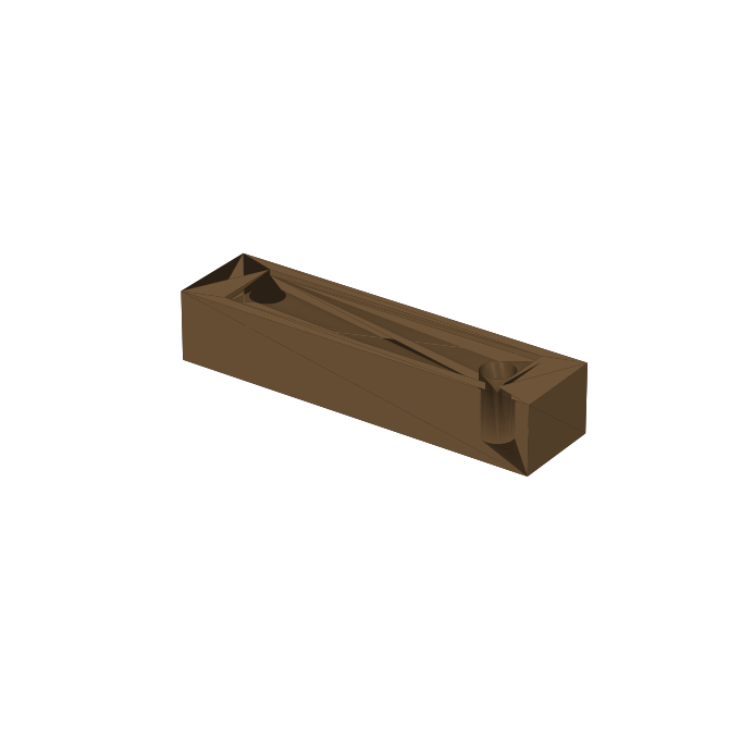
For: the plan’s ¾″ × ¾″ × 3″ hold-down across the stock’s top flat.
The bar has two clearance holes 2″ apart, matching an insert pair in the bed (¼-20 inserts, 1″ either side of center), and a shallow pocket for a cork or rubber pad. Print it with the pocket facing up, then flip it over when you fit the pad. Pair it with two fluted knobs, each with a hex pocket that captures a ¼-20 hex-head bolt.
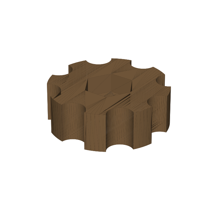
hold_down_bar.stl · print 1 + hold_down_knob.stl · print 2 · hardware: two ¼-20 × 1¼″ hex-head bolts (length to suit your inserts), cork or rubber pad
Pegged fence
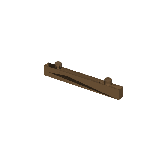
For: keeping the stock square to the hinge line without taping a fence on.
A ¼″ × ½″ strip with Ø6 mm pegs that drop into the bed’s ¼-20 inserts on the 2″ pitch, so it registers the same way every time. Print pegs up. Two two-peg segments plus one single-peg end piece cover the five pairs at 7, 9, 11, 13 and 15″ from the pin. The strip is ¼″ thick (the plan’s ⅛″ hardboard fence is thinner) because the peg needs the width; account for that when you set the stock against it.
The hold-down bar uses an insert pair across the bed, so leave that pair’s fence peg out — stop the fence before the bar.
fence_pair.stl · print 2 + fence_single.stl · print 1 · no hardware
DW745 saw cart
These are fit-to-your-hardware starting points. The turnbutton and hook are generic; the foot cup and rear-port adapter use estimated measurements from the plan.
Turnbutton
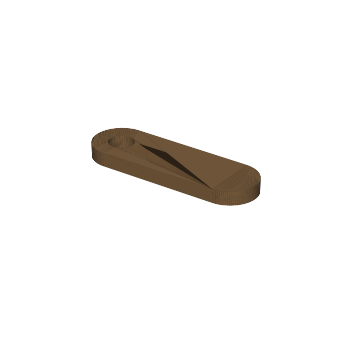
For: holding the lift-off front skirt panel against its foam gasket.
A 38 × 12 mm rounded tab, 4 mm thick, with a Ø5.4 mm hole for a #10 screw. A quarter turn clamps the panel; turn it back to lift the panel off.
turnbutton.stl · print 6 (plan calls for 4–6) · hardware: #10 × 1″ wood screw each
Wall hook
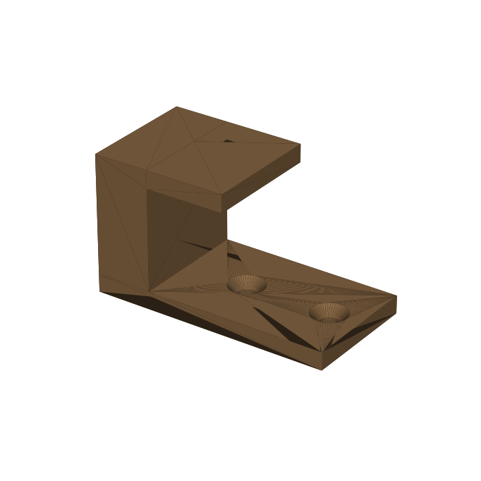
For: hanging the fence, miter gauge and cord on the cart’s right side.
A J-hook on a 60 × 30 mm plate with two countersunk screw holes. Mount it with the long axis vertical, plate against the wall, so the arm projects out and the lip rises at its end. Print 3.
wall_hook.stl · print 3 · hardware: two #8 flat-head wood screws each
Foot locator cup
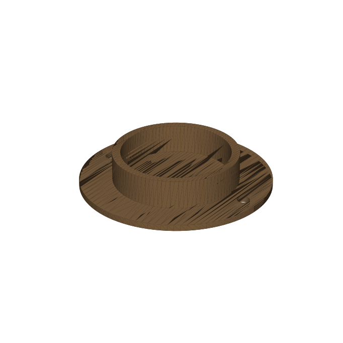
For: locating the saw on the support rails by its own weight, replacing the hold-down knobs the skirt would hide.
A Ø40 mm cup, 14 mm deep, on a Ø70 mm flange with two screw holes. The Ø40 mm foot diameter is an estimate — measure the saw’s rubber feet, set FOOT_D in the script, and regenerate. The plan also suggests a TPU liner; print that separately if you want one.
foot_cup.stl · print 4 · hardware: two #8 wood screws each
Rear-port adapter
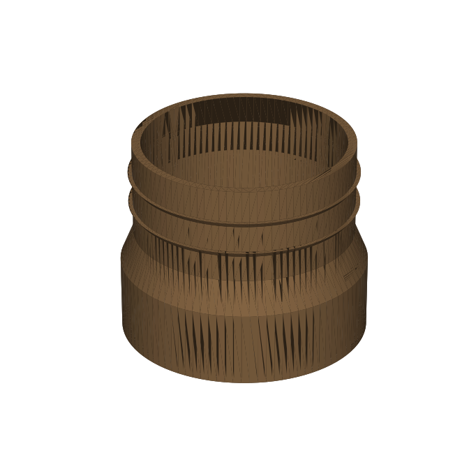
For: carrying the saw’s rear dust port to a 2½″ hose.
A socket (inside diameter 65.0 mm) that slips over the saw’s port, a short cone, and a ribbed spigot that a 2½″ hose pushes over. The 64.5 mm port diameter is the plan’s measurement from one Type 4 saw — measure yours, set SAW_PORT_OD, and regenerate. Print it upright, socket down.
rear_port_adapter.stl · print 1 · hardware: hose clamp
Table saw (any SawStop)
These are model-agnostic: they use the miter slot (standard ¾″ × ⅜″, 19.05 × 9.5 mm — measure yours to confirm) or the flat table. Nothing here replaces the saw’s guard, riving knife or brake; the push devices are accessories.
Safety. Push blocks and push sticks sit between your hand and the blade. Printed PETG is not rated for that: inspect before each use, discard anything cracked or crazed, never print them in PLA, and keep a commercial push block as a backup. Print the first one and push scrap with the saw off before trusting the shape.
Push block
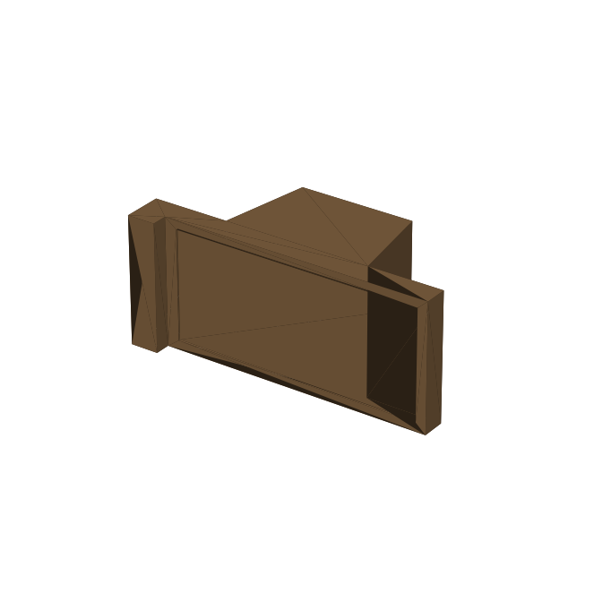
For: pushing stock past the blade under your hand’s full control.
A heel-and-toe block: a raised grip, a flat base for pressure on the stock, and an 8 mm heel at the back that catches the end of the workpiece so you push it rather than rubbing it. The base underside has a shallow pocket for a ⅛″ rubber pad (spray adhesive). Print it standing on its side (the profile lies flat on the bed); it is solid and fairly heavy, so use 3–4 perimeters and 20–30% infill.
push_block.stl · print 2 · hardware: ⅛″ rubber pad
Push stick
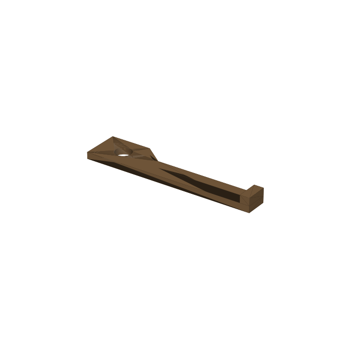
For: narrow rips, where there’s no room for a block between the blade and the fence.
A 250 mm stick with a wide handle (finger hole included), a slim shaft and a 15 mm hook at the tip that catches the back of the stock. Print it flat with the hook pointing up. The hook is only 15 mm deep, so it is for stock about ¾″ and thicker; for thin stock, use a block.
push_stick.stl · print 2 · no hardware
Featherboard (prototype)
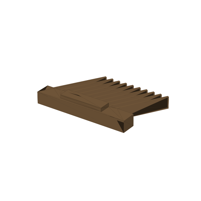
For: holding stock against the fence on rips.
Ten fingers leaning 30° toward the feed, on a base with a friction-fit miter-slot runner. This one is a prototype and is friction-only: a plain miter slot has no undercut, so there is nothing for a printed part to lock against, and the runner’s two crush ribs give a light grip. Treat it as a hold-down for light work, not as a kickback preventer, and test-fit it in a scrap slot first — tune RUNNER_CLEAR and CRUSH_RIB in the script until it needs a firm push. If you want a positive lock, bolt the base to a commercial expanding miter bar instead. Print it upside down (runner pointing up) so the fingers stand as vertical walls and flex along their layers.
featherboard.stl · print 1 · no hardware
Setup depth blocks
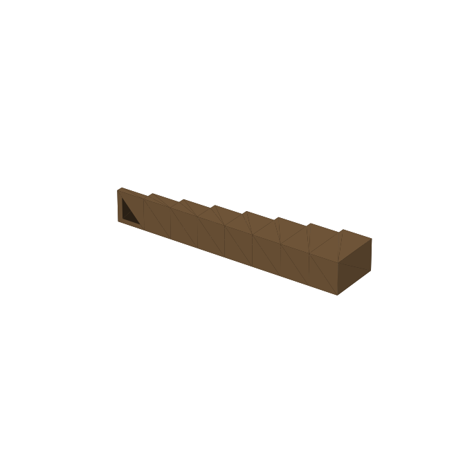
For: setting blade height or dado depth without a ruler.
Eight steps, ⅛″ to 1″ in ⅛″ increments. Stand a block next to the blade, lay a straightedge across it, and raise the blade until it just touches. Print it on its side so the heights lie in the print plane, and check them with calipers once.
setup_steps.stl · print 1 · no hardware
90° / 45° blade-angle checker
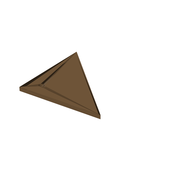
For: a quick check that the blade is square to the table (and at 45°) after you tilt it.
A 100 mm right isosceles triangle, 6 mm thick. Stand a leg on the table and the other against the blade body (between the teeth). The accuracy is only as good as your printer, so check it against a known-good square before relying on it.
angle_checker.stl · print 1 · no hardware
Crosscut-sled runner
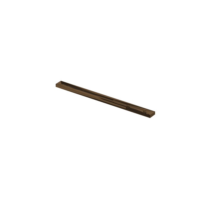
For: the miter-slot bars of a crosscut sled.
The tenoning jig uses one of these. A 240 mm segment, 18.6 mm wide (0.45 mm under the slot width) and 8.8 mm tall so it stays below the table surface, with six M5 nut pockets on a 40 mm pitch. Lay the sled base on the runners and screw down through it with M5 flat-head machine screws into the nuts. Print 4 and butt them end to end for two 480 mm runners. A runner this tight is a clearance fit, so tune it with masking tape or thin shims until it slides without side play, and keep the sled’s runners parallel to each other.
sled_runner.stl · print 4 · hardware: 6 M5 nuts and M5 × 25 flat-head screws per segment
Tenoning jig
These print the parts of the Miter-Slot Tenoning Jig; the wood and the clamp are on that page. It also uses one sled runner.
Tenon shim set
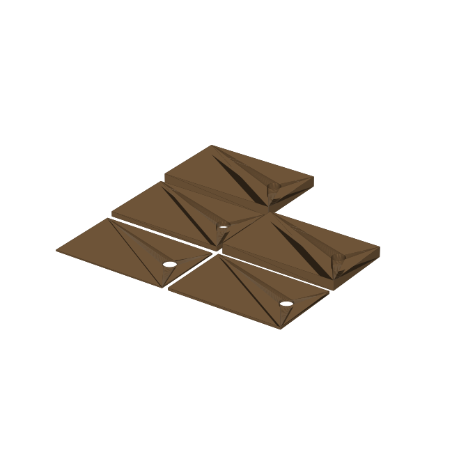
For: setting the tenon thickness: s = A − (t + T) ÷ 2, stacked between the fence and the stock.
Five plates — 1/16″, 1/8″, 1/4″, 1/2″ and 1/2″ — laid out on one bed (226 × 222 mm), so any 1/16″ step from 0 to 1-7/16″ is reachable. Print them flat; the thickness is set by layer count, so check each plate with calipers and adjust the print scale or layer height until they match. Each has a pull hole. Print two sets: one for the foot of the fence and one near the clamp.
tenon_shims.stl · print 2 · no hardware
Fence bracket
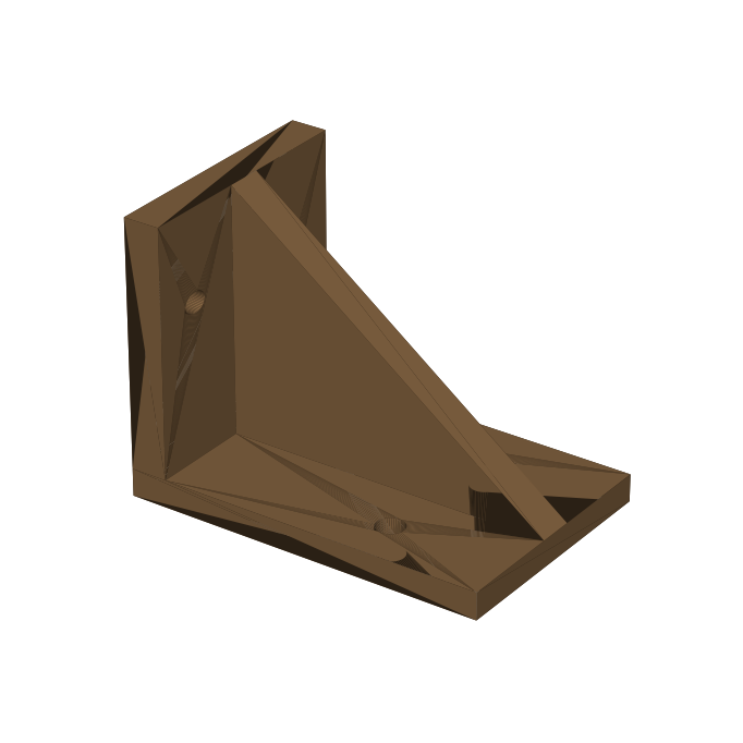
For: holding the fence square to the base.
A right-angle bracket with a web and two screw holes per flange (Ø4.6 mm, for #8 screws). Screw it into the base and the back of the fence, one at each end. Print it on the base flange.
jig_bracket.stl · print 2 · hardware: four #8 × 1″ wood screws each
Jig handle
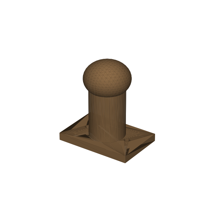
For: pushing the jig past the blade.
A flange with two screw holes, a 28 mm post and a rounded top. Screw it to the base behind the fence.
jig_handle.stl · print 1 · hardware: two #8 wood screws
Not yet designed
The plans also call for these printed parts; none of them has an STL yet:
- Scarf jig: the end-alignment gauge and the beam handles.
- Table saw: a flip-stop and a sled stop block; a positively locking featherboard.
- Saw cart: brush retainers, switch bezel, inlet filter frame with sliding shutter, the 4 × 4 × 2½″ wye, manifold collar, collector adapter, cove strips and the cyclone lid.